USB Host Port Installation
The steps you will need to complete will be based on what RP2040 board you are using and they may differ immensely. Some boards will require you to solder additional wires and connect peripheral boards onto your board. Others will have the host port already installed and no additional hardware steps will be required.
At the minimum, the following requirements are true for all RP2040 boards.
- 2 GPIO pins that are sequential (i.e.
GPIO Pin XandGPIO Pin X+1) and NOT in series/parallel with any capacitors or large, non-termination resistors - A 5V pin (i.e.
VBUS,VCC,+5V, etc.) - A ground pin (i.e.
GND)
You may need the following additional hardware to complete the installation. What you will need specifically will depend on your specific board configuration.
-
Solder and Soldering Iron
-
Wires to connect to the USB A port
-
Wire terminators to connect to your GP2040-CE Board
-
A USB Host board breakout board or an extra USB Cable
- Generic USB 2.0 Host Port
- USB Passthrough Board
Example Wiring
noteWhile this example wiring guide uses a Raspberry Pi Pico, the general principle applies to ALL RP2040 based boards.
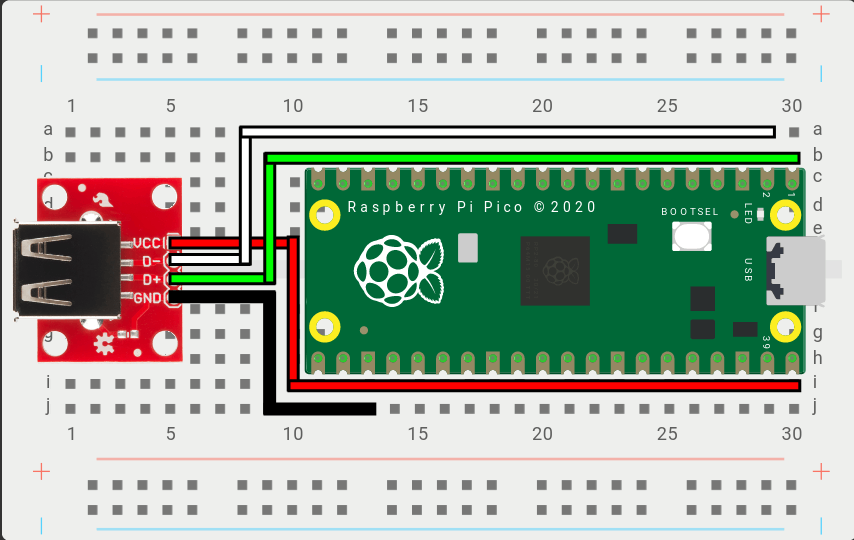
VCC- Connects to 5V power (Example: VBUS on the Raspberry Pi Pico)D+- Connects to theD+GPIO Pin above, set in the Web Configurator. (Example: GPIO0 on the Raspberry Pi Pico)D-- Connects to theD-GPIO Pin above, automatically set based on D+. (Example: GPIO1 on the Raspberry Pi Pico)GND- Connects to a ground pin, anyGNDpin will work. (Example: GND on the Raspberry Pi Pico)
noteFor
D+andD-, any set of GPIO pins can be used from the RP2040. However, there is a requirement thatD-GPIO must immediately precede or followD+(i.e.D+= GPIO Pin X ->D-must be X+1 or X-1).Example Wiring
Step 1: Take the USB passthrough board and place it on a clean surface.
Step 2: Take one of the cables and place it on a clean surface.
noteThe cables are JST 2.00mm 2pin same direction cables that are 10cm (100mm) in length. They can be made by hand or purchased directly from a variety of sellers on AliExpress. If you plan on installing the USB passthrough board somewhere else in your case you may want to get longer cables. For this install guide you will need three of the cables.
Step 3: Connect one end of the first JST 2.00mm 2pin cable into the socket labeled 5V IN on the USB passthrough board.
noteThe direction of the cable does not matter as they are all same direction cables.
Step 4: Connect the other end of the first JST 2.00mm 2pin cable to the socket labeled 5v OUT on the RP2040 Advanced Breakout Board.
Step 5: Connect one end of the second JST 2.00mm 2pin cable into the socket labeled D+ OUT on the USB passthrough board.
Step 6: Connect the other end of the second JST 2.00mm 2pin cable to the socket labeled OPTION 5 on the RP2040 Advanced Breakout Board.
noteYou can use other option sockets for this as well, but for the sake of this installation guide we will be using Option 5 and Option 6.
Step 7: Connect one end of the third JST 2.00mm 2pin cable into the socket labeled D- OUT on the USB passthrough board.
Step 8: Connect the other end of the third JST 2.00mm 2pin cable to the socket labeled OPTION 6 on the RP2040 Advanced Breakout Board.