Wiring
Custom builds using these microcontroller boards may have different GPIO pin mappings from the ones listed below, depending on the vendor.
Resetting through the Web Configurator may result in incorrect GPIO pin mappings so it is recommended to speak with the vendor first.
These are the pinouts of the GP2040-CE supported microcontroller board that are precompiled and available for download.
They do not cover all cases and your particular RP2040 based board will likely had a different pin out, which depends entirely on how the board manufacturer decided to make the board. Exercise caution and do not assume that the pins on your board match the ones listed here.
None of these pinouts are permanent. The pinouts can be changed to suit your needs through the Web Configurator - GPIO Pin Mapping.
Raspberry Pi Pico
The Raspberry Pi Pico pinout can also be used on clone boards with the same form factor and pinout, such as the Pimironi Pico LiPo and the Waveshare RP2040-Plus.

SparkFun Pro Micro - RP2040

Waveshare RP2040-Zero

Adafruit KB2040

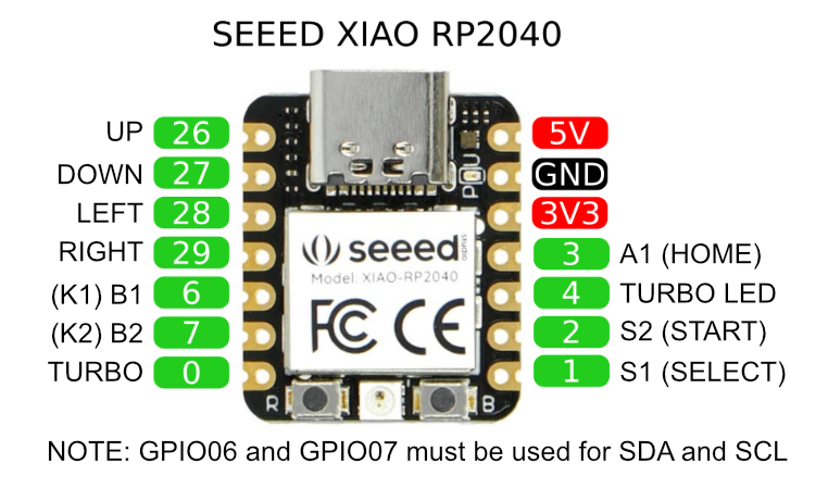
Seeed XIAO RP2040
Buttons
GP2040-CE configures the input GPIO pins to be pulled up, expecting the button to short the pin to the ground when pressed.
You can either wire each button using two wires (one to the GPIO pin, the other to the ground):

Or you can chain the groud wire from button to button, e. g. by crimping two wires at once to a FASTON terminal or by soldering two wires to a button pin. The other contact of each button must be connected to a separate GPIO pin:

PWM LEDs
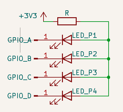
The PWM player LED pins are configured similarly: the pin is shorted to the ground when active and pulled up otherwise. This means the LED anodes must be connected to the +3.3V output of the microcontroller and each cathode to its GPIO pin, in an arrangement called common anode. A current-limiting resistor must be inserted into the circuit to protect the GPIO pins; use an online calculator to compute its value if unsure. The maximum safe current is cca 20mA.