Analog
Purpose: This add-on is intended for the use of a hardware analog joystick with GP2040-CE for the left and right analog sticks of the gamepad.
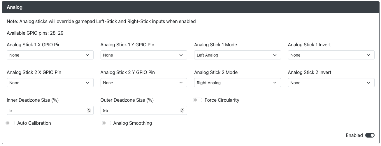
Web Configurator Options
Analog Stick 1 X Pin- The GPIO pin used for the Analog joystick 1 X value. Only ADC pins 26, 27, 28 and 29 are allowed here.Analog Stick 1 Y Pin- The GPIO pin used for the Analog joystick 1 Y value. Only ADC pins 26, 27, 28 and 29 are allowed here.Analog Stick 1 Mode- Choose if Analog joystick 1 is to be used for Left Analog or Right Analog.Analog joystick 1 Invert- Choose if you would like to flip the X or Y axis Analog Stick 1 inputs (or both).Analog joystick 2 X Pin- The GPIO pin used for the Analog Stick 2 X value. Only ADC pins 26, 27, 28 and 29 are allowed here.Analog joystick 2 Y Pin- The GPIO pin used for the Analog Stick 2 Y value. Only ADC pins 26, 27, 28 and 29 are allowed here.Analog joystick 2 Mode- Choose if Analog Stick 2 is to be used for Left Analog or Right Analog (must be different than Analog Stick 1).Analog joystick 2 Invert- Choose if you would like to flip the X or Y axis Analog joystick 2 inputs (or both).Inner Deadzone Size (%)- Enter the % value of inner dead zone you would like on the analog joysticks.Outer Deadzone Size (%)- Enter the % value of outer dead zone you would like on the analog joysticks.Forced Circularity- Force the analog joysticks to be bound within a perfect circle. This can be beneficial for certain games. However, be aware that this may negatively impact some games which account for sticks moving outside of a circle.Auto Calibration- Automatically centers the analog joysticks. This works by reading in the offset from center during boot and then accounts for that until the next power cycle. This can be helpful for analog joysticks experiencing drift.
Hardware
Requirements
A minimum of one hardware analog joystick is required for the use of this add-on. Each joystick will have at least 4 pins, one for each of the following.
- Reference Voltage (ADC_VREF/3.3V)
- X-Axis Input Voltage (Vx)
- Y-Axis Input Voltage (Vy)
- Ground (GND)
Each axis input voltage pin requires an Analog to Digital Converter (ADC) pin to operate. As such, some boards may have a limit on the maximum number of possible joysticks that can be used (e.g. the Raspberry Pi Pico only has 3 ADC pins available so only 1 joystick can be used).
The analog joystick may have an additional pin for the joystick button. This can be connected to any GPIO pin and used as a regular button.
Installation
Connect the pins of the analog joystick to the board as follows and then set the GPIO pin values in Web Configurator > Configurations > Add-Ons > Analog.
- Reference Voltage (ADC_VREF/3.3V) -> ADC_VREF/3.3V Pin
- X-Axis Input Voltage (Vx) -> Any ADC GPIO Pin
- Y-Axis Input Voltage (Vy) -> Any ADC GPIO Pin
- Ground (GND) -> Any GND Pin
The specific location of the ADC pins on your board will vary depending on the design and manufacturer, but they will always be one of the following GPIO pins on the RP2040
- GPIO 26
- GPIO 27
- GPIO 28
- GPIO 29
Miscellaneous Notes
Both potentiometer and Hall Effect based joysticks are supported, provided that they use a 3.0-3.3V reference voltage and output voltages in the range of 0-3.3V as an input for the RP2040. This is because the GPIO pins for the RP2040 utilize 3.3V logic and are not 5V-safe.