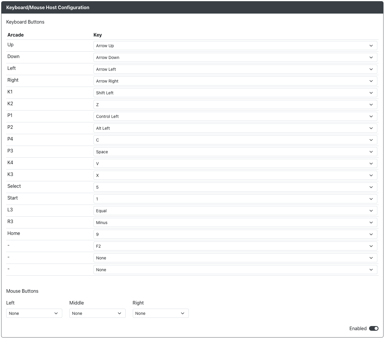
Keyboard Host Configuration
Select the button labels to be displayed in the usage guide:
Purpose: This add-on is intended to allow you to use a keyboard with GP2040-CE to be used with GP2040-CE supported systems.

Web Configurator Options
The Data, 5V Enable, and Pin Orientation options for USB host ports are now configured in Configuration > Peripheral Mapping - USB Host.
Default Keybindings
| GP2040 | Key |
|---|---|
Up | Arrow Up |
Down | Arrow Down |
Left | Arrow Left |
Right | Arrow Right |
B1 | Shift Left |
B2 | Z |
B3 | Control Left |
B4 | Alt Left |
L1 | C |
R1 | Space |
L2 | V |
R2 | X |
S1 | 5 |
S2 | 1 |
L3 | Equal |
R3 | Minus |
A1 | 9 |
A2 | F2 |
Function | None |
Hardware
Requirements
This add-on requires that you have a USB host port available on your device connected to GPIO pins on the RP2040 board. There are a number of methods to do so.
See USB Host Port Installation for more information on the requirements for adding a USB host port to your controller.
Installation
- Generic USB 2.0 Host Port
- USB Passthrough Board
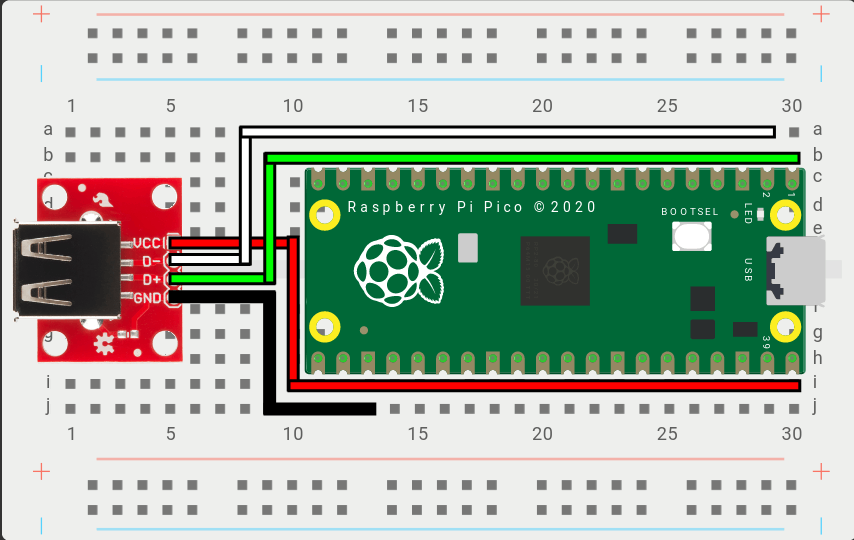
Example Wiring
While this example wiring guide uses a Raspberry Pi Pico, the general principle applies to ALL RP2040 based boards.

VCC- Connects to 5V power (Example: VBUS on the Raspberry Pi Pico)D+- Connects to theD+GPIO Pin above, set in the Web Configurator. (Example: GPIO0 on the Raspberry Pi Pico)D-- Connects to theD-GPIO Pin above, automatically set based on D+. (Example: GPIO1 on the Raspberry Pi Pico)GND- Connects to a ground pin, anyGNDpin will work. (Example: GND on the Raspberry Pi Pico)
For D+ and D-, any set of GPIO pins can be used from the RP2040. However, there is a requirement that D- GPIO must immediately precede or follow D+ (i.e. D+ = GPIO Pin X -> D- must be X+1 or X-1).
Example Wiring
Step 1: Take the USB passthrough board and place it on a clean surface.
Step 2: Take one of the cables and place it on a clean surface.
The cables are JST 2.00mm 2pin same direction cables that are 10cm (100mm) in length. They can be made by hand or purchased directly from a variety of sellers on AliExpress. If you plan on installing the USB passthrough board somewhere else in your case you may want to get longer cables. For this install guide you will need three of the cables.
Step 3: Connect one end of the first JST 2.00mm 2pin cable into the socket labeled 5V IN on the USB passthrough board.
The direction of the cable does not matter as they are all same direction cables.
Step 4: Connect the other end of the first JST 2.00mm 2pin cable to the socket labeled 5v OUT on the RP2040 Advanced Breakout Board.
Step 5: Connect one end of the second JST 2.00mm 2pin cable into the socket labeled D+ OUT on the USB passthrough board.
Step 6: Connect the other end of the second JST 2.00mm 2pin cable to the socket labeled OPTION 5 on the RP2040 Advanced Breakout Board.
You can use other option sockets for this as well, but for the sake of this installation guide we will be using Option 5 and Option 6.
Step 7: Connect one end of the third JST 2.00mm 2pin cable into the socket labeled D- OUT on the USB passthrough board.
Step 8: Connect the other end of the third JST 2.00mm 2pin cable to the socket labeled OPTION 6 on the RP2040 Advanced Breakout Board.
Miscellaneous Notes
As long as the keyboard has a USB plug, any keyboard should work with this addon, including wireless USB keyboards.
Due to current implementation of Pico-PIO-USB and the add-on system, the following limitations are present.
- The keyboard is limited to only as many inputs as listed above. All other keys on the keyboard will not function and will send no inputs to the system reading inputs.
- The keyboard is limited to 6 key rollover, meaning that a maximum of 6 keyboard keys can be activated at a time. This is the case regardless if the keyboard being used normally has N key rollover (NKRO).
- The keyboard is unable to affect the Input Mode on boot. The Input Mode must either be set using
Web Configurator > Settingsor an additional switch on the GP2040-CE device using the add-on.