Peripheral Mapping
Here you can assign the GPIO pins necessary for using input modes, peripherals, and add-ons that require I2C and a USB host port. These include, but are not limited to
- PS4 Input Mode
- PS5 Input Mode
- OLED Display
- I2C Analog ADS1219
- Xbox One Input Mode
- Keyboard/Mouse Host Add-on
Click on the (i) tool tip in the Web Configurator for more information on the various settings
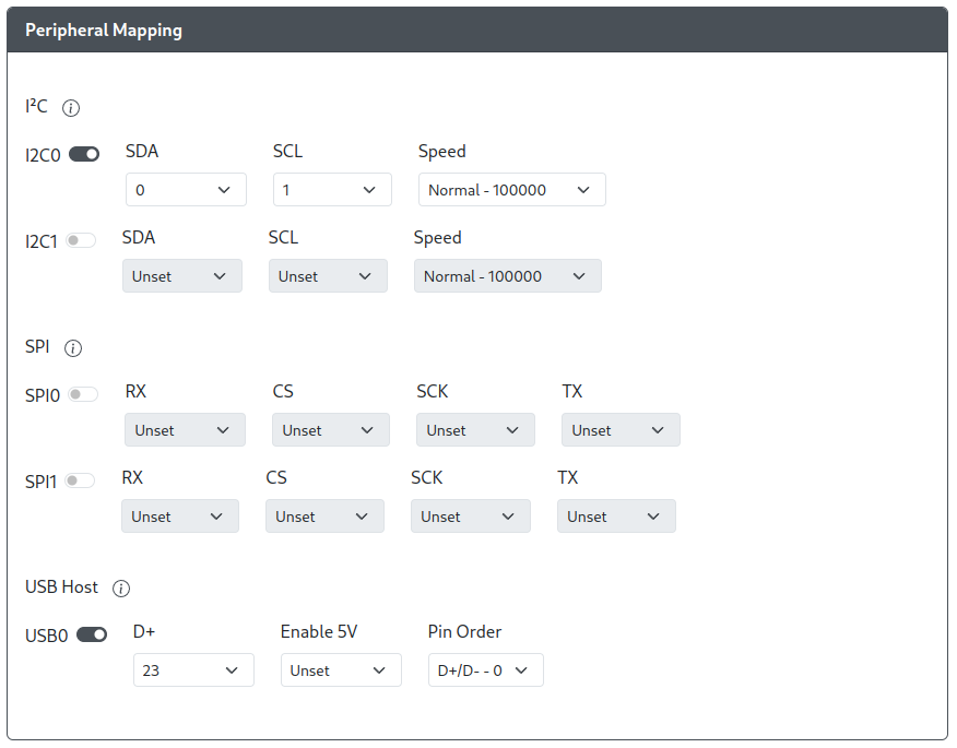
I2C
Each I2C block, I2C0 and I2C1, has separate settings and each must be configured before using the respective I2C block. These must be configured properly before any feature or add-on that uses I2C can be used.
Toggle- This will toggle a specific I2C block on and offSDA- The GPIO pin used for Serial Data (SDA).SCL- The GPIO pin used for Serial clock (SCL).Speed- Sets the speed of I2C communication.Normal - 100000Fast - 400000Fast Plus - 800000
The SDA and SCL pins must match a pair found on the table below for each I2C block. If this is not configured correctly, your I2C devices will not function properly.
| SDA | SCL | I2C Block | SDA | SCL | I2C Block |
|---|---|---|---|---|---|
| GP00 | GP01 | I2C0 | GP02 | GP03 | I2C1 |
| GP04 | GP05 | I2C0 | GP06 | GP07 | I2C1 |
| GP08 | GP09 | I2C0 | GP10 | GP11 | I2C1 |
| GP12 | GP13 | I2C0 | GP14 | GP15 | I2C1 |
| GP16 | GP17 | I2C0 | GP18 | GP19 | I2C1 |
| GP20 | GP21 | I2C0 | GP22 | GP23 | I2C1 |
| GP24 | GP25 | I2C0 | GP26 | GP27 | I2C1 |
| GP28 | GP29 | I2C0 | ---- | ---- | ---- |
SPI
Each SPI block, SPI0 and SPI1, has separate settings and must be configured before using the respective SPI block. These must be configured properly before any feature or add-on that uses SPI can be used.
Toggle- This will toggle a specific SPI block on and offRX- The GPIO pin used for MISO, to receive data.CS- The GPIO pin used for Chip Select (CS).SCK- The GPIO pin used for Serial Clock (SCK).TX- The GPIO pin used for MOSI, to send data.
The pins must match a set found on the table below for each SPI block. If this is not configured correctly, your SPI devices will not function properly.
| RX | CS | CLK | TX | SPI Block |
|---|---|---|---|---|
| GP00 | GP01 | GP02 | GP03 | SPI0 |
| GP04 | GP05 | GP06 | GP08 | SPI0 |
| GP08 | GP09 | GP10 | GP11 | SPI1 |
| GP12 | GP13 | GP14 | GP15 | SPI1 |
| GP16 | GP17 | GP18 | GP19 | SPI0 |
| GP20 | GP21 | GP22 | GP23 | SPI0 |
| GP24 | GP25 | GP26 | GP27 | SPI1 |
| GP28 | GP29 | ---- | ---- | SPI1 |
USB Host
There are not restrictions on which GPIO pins can be used for setting up a USB host port. You can pick any GPIO pin as long as it is available (not being used by any other feature) and the GPIO pin selected for D+ has a GPIO pin immediately following or preceding it that can be used for D- (e.g. GPIO X and GPIO X+/-1).
Toggle- This will toggle the USB Host Port on and offD+- The GPIO Pin used to carry Data Plus between the USB Host Port and RP2040Enable 5V- The GPIO Pin used to enable 5V power to the host port on the board.Pin Order- This setting is based on the order that the Data pins are connected to sequential GPIO pinsD+/D-- The GPIO pins are set such that, sequentially,D+is immediately followed byD-(e.g. D+ = 0. D- = 1)D-/D+-The GPIO pins are set such that, sequentially,D+is immediately preceded byD-(e.g. D+ = 29, D- = 28)
Most boards do not require this to be set. This is only applicable to a small number of boards (e.g. Adafruit RP2040 Feather USB Host) as they possess pins for enabling and disabling 5V port on the USB host port.