Display Configuration
GP2040-CE supports the use of a display module such as an OLED with a SSD1306, SH1106, or SH1107 display IC.
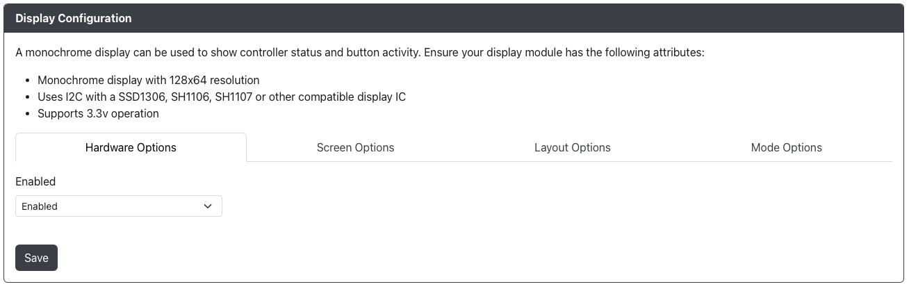
Hardware Options
Enabled- Turns on/off the display module.
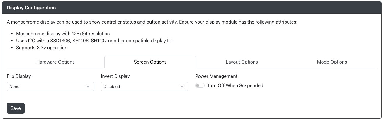
Screen Options
Flip Display- Allows you to flip or mirror the display in a variety of ways.Invert Display- Inverts the pixel colors, effectively giving you a negative image when enabled.Power Management- Allows you to turn off the display when suspended.
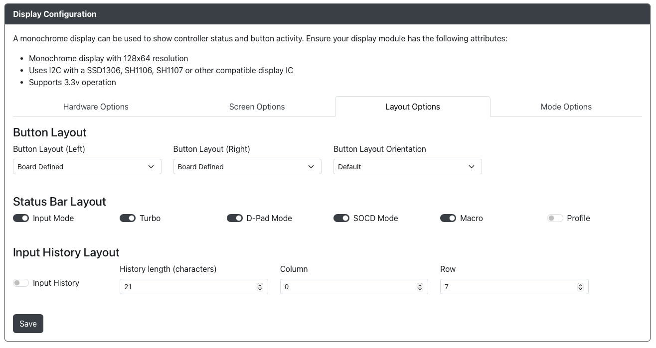
Layout Options
Be sure to pick left and right layouts that match. Some layout combinations result in overlapping buttons on the screen.
Button Layout
Button Layout (Left)- Changes the onscreen layout for the left side of the display and stick.Button Layout (Right)- Changes the onscreen layout for the right side of the display and stick.Button Layout Orientation- Allows you to flip or switch the overall layout.
Status Bar Layout
Input Mode- Allows you to show or hide theInput Modeon your display.Turbo- Allows you to show or hide theTurbosetting on your display.D-Pad Mode- Allows you to show or hide theD-Pad Modeon your display.SOCD Mode- Allows you to show or hide theSOCD Modeon your display.Macro Mode- Allows you to show or hide theMacro Modeon your display.Profile- Allows you to show or hide theProfilename on your display (if profiles are enabled).
Input History Layout
Input History- Allows you to show or hide a a running input history.
Input history has the following options:
History length (characters)- The number of characters to display on the screen forInput History(21 by default).Column- The column position on the screen to startInput Historyat (0 by default).Row- The row position on the screen to startInput Historyat (7 by default).
It is recommended to leave History length (characters), Column and Row as they are unless you are working on a custom display.
Mode Options
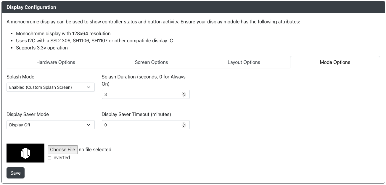
Splash Mode- Enables or disables a splash screen displaying when the unit is turned on.Splash Duration- Sets the amount of time the splash screen displays for on boot.Display Saver Timeout- Will cause the display to turn off after the specified number of minutes. Pressing any input will cause the display to turn back on.Choose File- Upload your own image to be used for the splash screen.
Custom Splash Screen
It is recommend that you use a two color 128x64 image (or one that is sized appropriately for your display). Uploading any other type of image will result in a conversion and sizing of the image automatically.
Supported Formats: BMP, GIF, JPG, JPEG, PNG, WEBP
Animated GIFs are not supported at this time.
Check out our collection of great custom splash screens from the community HERE
Display Elements

This area contains an explanation of display elements and provide an example for how it may appear on your device.
Top Row
Going from left to right, the display elements are
- Input Mode - Displays the current input mode
XINPUT- XInputSWITCH- Nintendo SwitchSWPRO- Nintendo Switch Pro ControllerDINPUT- PS3/DirectInputHID-KB- KeyboardPS4- Controller Mode set asController, will change toPS4:ASon successful authenticationPS4:AS- PS4 Input Mode add-on successfully authenticatedPS5- Controller Mode Set asArcade Stick, will change toPS5:ASon successful authenticationPS5:AS- PS5 Input Mode add-on successfully authenticatedXBONE- Xbox One compatible with Xbox One Input ModeOGXBOX- Original XBoxGEN/MD- Sega Genesis/MegaDrive MiniNGMINI- NEOGEO miniPCE/TG- PC Engine/Turbografx 16 MiniEGRET- EGRET II MiniASTRO- ASTROCITY MiniPSC- Playstation Classic
- Turbo - Will display
T##when Turbo is enabled where ## is the number of presses per second - DPad Mode - Displays the current DPad Mode
D- DPad DigitalL- DPad Left AnalogR- DPad Right Analog
- SOCD Cleaning Mode - Displays the current SOCD cleaning Mode
SOCD-U- SOCD Up PrioritySOCD-N- SOCD NeutralSOCD-L- SOCD Last WinSOCD-F- SOCD First WinsSOCD-X- SOCD Cleaning Off
- Macros -
Mwill appear if Macros are enabled and this cannot be disabled.
Middle
The appearance of this area will depend on the particular configuration of your Button Layouts on the Left and Right sides
- Turbo Rings - When using the Turbo Mode is enabled on individual buttons, the buttons will have a smaller inner ring as an indicator. When disabled, this button will disappear.

Bottom
- Input History - Will display input history when the Input History add-on is enabled and configured